Theodolite: It was invented by Roemer, a Danish astronomer in 1690.
The instrument was used to observe the passage (transit) of stars across any
portion of the celestial meridian. About a century later it was modified to
suit the surveying requirements.
It is a most precise instrument
designed for the measurement of horizontal and vertical angles and has wide
applicability in surveying such as laying of horizontal angles, locating points
on line, prolonging survey lines, establishing grades, etc.
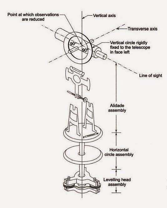 |
Figure shows three assemblies of
theodolite
|
Following three axis of
theodolite should always be perfectly perpendicular to each other, and by
considering this permanent adjustment of theodolite carried out.
1. Vertical
axis
2. Horizontal
axis
3. Line
of sight
Theodolite may be classified as:
1. Transit
theodolite
2. Non-transit
theodolite
Transit
theodolite is one in which the line of sight can be reversed by revolving the
telescope through 180◦ in the vertical plane.
Non-transit
theodolite are either plain theodolites or Y-theodolite in which the telescope
cannot be transited. The transit theodolite is mainly used and Y-theodolites
have now become obsolete.
Purposes for which a theodolite
can be used:
1. Measuring
the horizontal angles
2. Measuring
the vertical angles
3. Measuring
the deflection angles
4. Measuring
the magnetic bearings
5. Finding
the vertical height of an object
6. Measuring
the horizontal distance between two points
7. Finding
the difference of elevation between various points
8. Ranging
a line
Terms used in Theodolite
surveying:
1. Centering:
it involves setting the theodolite such that its vertical axis passes through
the station mark on the ground. It is done by means of a plumb line attached to
a hook below the instrument, or by optical plummet, if available. (Optical
plummet substitutes for a plumb bob when centering the instrument.)
2. Levelling:
The operation of levelling involves the plates being made horizontal with the
aid of bubble tubes or plate levels attached to them.
3. Transiting
(or plunging or reversing): It is a process of turning the telescope over the
horizontal axis through 180◦ in a vertical plane, making its upside down and
pointing in the opposite direction.
4. Face
left (bubble up): if the vertical circle is to the left of the observer when
sighting from the eyepiece end. The angle measured in this position is called a
face left observation. The bubble tube attached to the instrument lie above it.
5. Face
right (bubble down): if the vertical circle is to the right of the observer
when sighting from the eyepiece end. The angle measured in this position is
called a face right observation. The bubble tube attached to the instrument lie
below it.
6. Changing
face: it is the process of changing face from right to left. The face of
theodolite is changed by transiting the telescope first and then turning it
through 180◦.
7. Right
swing: it is made by turning the telescope to the right (or clockwise) in the
horizontal plane. The reading on the horizontal circle then increases.
8. Left
swing: it is made by turning the telescope to the left (or anti clockwise) in
the horizontal plane. The reading on the horizontal circle then decreases.
 |
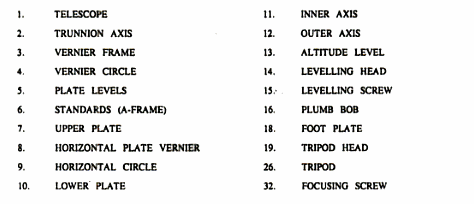
Figure: The essential
components of a transit theodolite
 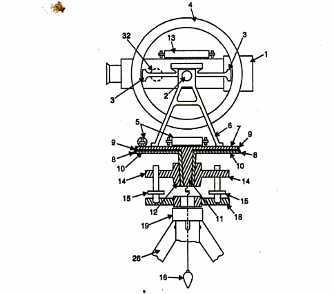
Figure: The essential
components of transit theodolite
Some important
terms:
Vertical axis:
It is the axis of rotation of telescope in horizontal plane.
Horizontal axis:
It is the axis of rotation of telescope in vertical plane. It is also known as
turnnion axis.
Ques. What are the permanent adjustment of theodolite?
Ans. A theodolite is said to be in permanent adjustment if
the the following requirements are fulfilled:
1.
The plate level axis is perpendicular to
vertical axis.
2.
The horizontal axis is perpendicular to vertical
axis.
3.
The line of sight coincide with optical axis of
the telescope.
4.
The axis of the altitude level is parallel to
the line of sight.
5.
When the line of sight is horizontal vertical
circle Vernier reads zero.
First
four requirements are the requirements among five fundamental axis and the
fifth one is about the vertical circle index.
Ques. What is the procedure to check the plate level axis is
perpendicular to vertical axis?
Ans. Following procedure is adopted:
1.
Set up the theodolite on a firm ground and
complete all temporary adjustment. See that the plate bubble is exactly in the
centre when the telescope is parallel to the two screws.
2.
Revolve the telescope by 180◦,
3.
If the instrument is in adjustment, bubble remains
in the centre, otherwise note down the number of divisions by which the bubble
has moved out.
Oues. Define for vertical axis, bubble axis, collimation
axis, horizontal axis?
Ans. Vertical axis:
It is the axis of rotation of telescope in horizontal plane.
Horizontal axis: It is the axis of rotation
of telescope in vertical plane. It is also known as turnnion axis.
Collimation axis: it is a line joining the
optical centres of objective lens and eyepiece.
Ques. What relationship exist among the above principal axes
of theodolite??
Ans. Principal axises of theodolite are perfectly
perpendicular to each other to maintain the permanent adjustment.
Ques. What are the fundamental lines of a transit?
Ans. Following are the fundamental lines of theodolite:
1.
Vertical axis
2.
Horizontal axis
3.
Line of sight or line of collimation
Ques. How is the principal of reversal applied while
adjusting the axis of plate bubble of a theodolite??
Ans. The principle of reversal sates that if there is any
error in a certain part of instrument, then it will be doubled by reversing
i.e. by revolving the telescope through 180◦. Thus apparent error becomes twice
the actual error on reversing.

Using the Principle of Reversal
following steps can be adopted:
1.
Set up the theodolite on a firm ground and
complete all temporary adjustment. See that the plate bubble is exactly in the
centre when the telescope is parallel to the two screws.
2.
Revolve the telescope by 180◦,
3.
If the instrument is in adjustment, bubble remains
in the centre, otherwise note down the number of divisions by which the bubble
has moved out.
Ques. Under what situation can there be difference between
the Vernier readings of horizontal circles of a theodolite? How will you
eliminate the error in one or both of them?
Ans. Difference in Vernier readings can occur
1.
If the centre of graduated horizontal circle
does not coincide with the centre of the Vernier plate. Reading against Vernier
will be incorrect. This can be eliminated by taking average of two readings.
2.
If there is imperfect graduations of the
horizontal circle. This can be minimized by taking mean of several readings
distributed over different portions of the horizontal circle.
3.
If the zeroes of the Vernier are not at the end
of the same diameter, this can be eliminated by taking mean of the two
readings.
Ques. Bring out the difference in
theodolite, if any, between the
a.
Horizontal axis and trunnion axis
b.
Line of collimation and line of sight.
Ans. Trunnion axis of a theodolite is the axis about which
the telescope and vertical circle rotate. It is the line passing through the
journals which fit into the bearings at the top of the standards. When this
line is horizontal, it becomes the horizontal axis of the instrument.
Line of sight is any line passing through
the eyepiece and the optical centre of the objective of telescope. Line of
collimation is an imaginary particular line joining the intersection of the
crosshair of the diaphragm and the optical centre of the objective. This line
should be perpendicular to the horizontal axis and should also be truly
horizontal when the reading on the vertical circle is zero and the bubble on
the telescope or on the Vernier frame is at the centre of its run.
Ques. What is the basic difference between temporary and
permanent adjustments of a theodolite?
Ans. Temporary adjustment are required to be made at each
station before taking readings. Permanent adjustments which usually last for a
long time etc. in proper relation to one another.
References:
Surveying, Volume 1 By Dr. B.C. Punmia, Ashok
Kumar Jain, Ashok Kr. Jain, Arun Kr. Jain
Surveying
And Levelling By Basak
Surveying,
Volume 1 By Duggal
The
Surveying Handbook By Russell
Charles Brinker
Surveying
and Levelling, Volume 1 By S. S.
Bhavikatti
Textbook
of Surveying By C Venkatramaiah
|